


CONTACT US


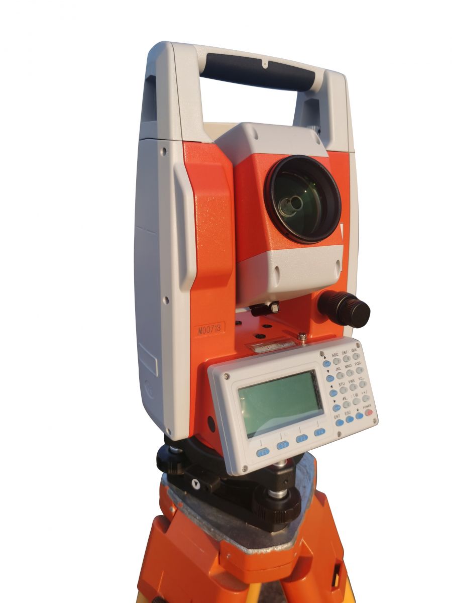
Details of improving orientation accuracy of total station
Coordinate orientation of total station is a necessary work for coordinate staking out and point position measurement in construction survey. Accidental errors can be reduced during coordinate staking out and point measurement through multiple alignment measurements, and fixed errors can be reduced through left and right disk observation, to improve measurement accuracy. However, due to the special properties of the total station, the orientation of the total station can only be determined once. If the view orientation error is 5 ", there is a high probability that you will also have an error of 5 "at all measuring points at this station. Ensuring the accuracy of orientation is the basic premise to ensure the accuracy of staking out point and measuring point.
According to our years of measurement experience, attention to details and measures for the directional accuracy of total station are summarized as follows:
1. Calibrate the compensator before orientation
The compensator of the total station usually needs to be calibrated frequently. Before observation, the total station should rotate 90°, 180°,270° to check the compliance of the compensator. When the deviation is found to be large, it can be immediately calibrated in the field, which generally takes only several minutes.
2. Calibration instrument alignment axis error
Alignment axis error, also known as 2C error, affects the horizontal Angle. This error can be eliminated by observing the left 1&2 and taking the median, but it is not appropriate to do that when measuring point position and coordinate staking out. Therefore, the instrument 2C error should be adjusted as small as possible in advance. We generally consider it safe to calibrate it to less than 2 seconds. It doesn’t need to be often corrected if there is no big turbulence.
How to calibrate the alignment axis error:https://youtu.be/W2Mdi7NB0ls
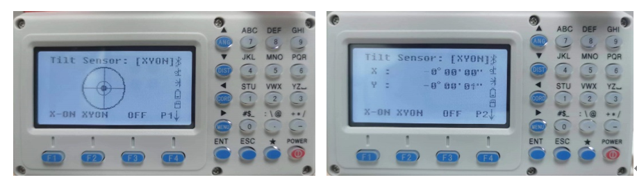
3. Verify the center and stability of bubbles before orientation
Usually when arriving at the control point, the surveyor will first centralize and level the total station. However, when the total station is set up for the first time, distance orientation generally takes time for a while, such as waiting for the prism to arrive at the measuring point, input station and back sight point coordinates, etc. The time generally takes several minutes to more than ten minutes. During this period, the instrument bubbles will generally have different degrees of deviation because the total station is just set up, the foot is not stable enough, the instrument just adapt to the outside temperature, or the surveyor will walk around the instrument. Therefore, the electronic bubble adjustment interface should be opened again to re-check and adjust the electronic bubble after the station coordinates and the view coordinates are set up and the instrument telescope aiming at the back sight point direction. The small movements will not affect the instrument alignment accuracy, don’t worry about it.
4.Aim repeatedly at the back sight point to determine orientation
A better way to manually aim at back sight point is to zoom in the observation target repeatedly (you can also aim at the center of the prism if the distance is relatively close). When you feel the best alignment, press the "Record" key of the instrument.
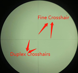
Many surveyors like to aim at the bottom of the pole for fear of its perpendicularity is not good enough, which is fine, but WE usually don't because we always have the perpendicularity of the pole calibrated in advance. If the verticality of the older pole is uncertain, or when the pole needs to be extended relatively high, you can also aim at the bottom of the pole through the gap. The crosshairs of total station telescopes have two types: duplex crosshairs and fine crosshair. Fine crosshair is generally used to aim. However, when aiming at the bottom of the pole, we can generally jam the target with duplex crosshairs, so that it will be more accurate.
5. Remeasurement after orientation
It is necessary to remeasure the coordinates of back sight points after orientation, and the coordinate and elevation values of retest should be recorded completely and compared with the design results.
Experienced surveyors can judge the backtracking error which is the observer's alignment error or control point error, according to the directional azimuth angle.
__________________________________________________________________________________________________________________________________
分享
SUPPORT
FOLLOW US


© 2023 Guangzhou Geosurv InformationTechnology Co., Ltd copyright ![]() 粤公网安备44011202003238号 粤ICP备20072763号-1
粤公网安备44011202003238号 粤ICP备20072763号-1
